|
|
|
|
|
|
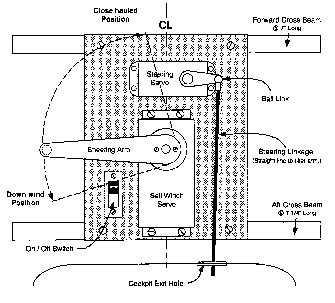
The Crossbeams are cut to length and beveled to fit the hull. The shorter beam goes forward, longer beam aft. Measure and center the board on the beams. Mount the board on the beams using four of the screws that came in the upgrade kit. The aft beam must not interfere with the large servo opening.
Sail Winch Servo (The larger one.) Install the four black rubber bushings to the servo corners. Push the brass sleeves down through the bushings. Install the servo on the board using the screws provided in the electronics bag.
Install the Rudder Servo the same way.
The On/Off Switch is mounted on the board as follows: Remove the two screws located on the face of the switch. Separate the faceplate from the main switch body. Locate the switch body on the underside of the electronics board with the short wire leading aft. Mount the faceplate on top of the board and insert the two screws into the switch body. Tighten up the screws and test operate the switch. The switch should be "On" when the switch lever is forward.
Remove the two servos after they have been test fit. Leave the switch mounted.
Remove one of the screws from each crossbeam for the next step.
Rotate the beams to insert the board into the hull through the hatch. Re-align the beams and install the screws.
Position the board's forward edge 3/8 inch from the brass keel pipe. Measure from the deck down to the top
of the platform on each side to get the platform level.
Clearly mark on the hull the four footprints of the ends of the beams
Sand and clean the footprint area to assure a good bond.
Slide the board aft far enough to give easy access to the keel trunk.
Consider squaring off the front of the hatch opening to give access to the forward beam screws. This allows easier removal of the mounting board if that becomes necessary. Alternatively, drill two holes for a screwdriver within the hatch boundaries defined by the Hatch Rail, Part 5.
OPTION NOTE -
Another way to allow the easy removal of the radio board is to open the forward crossbeam rail screw holes to form notches. Now after the board and supports have been installed, by removing the aft screws you can remove the radio board. For more information and photos check out https://www.rcyachts.com/Build/radioboard.htm
BACK NEXT PAGE
|
|
|
|
|
|